 Choisissez votre agence
 Choisissez votre agence
Home > Solutions
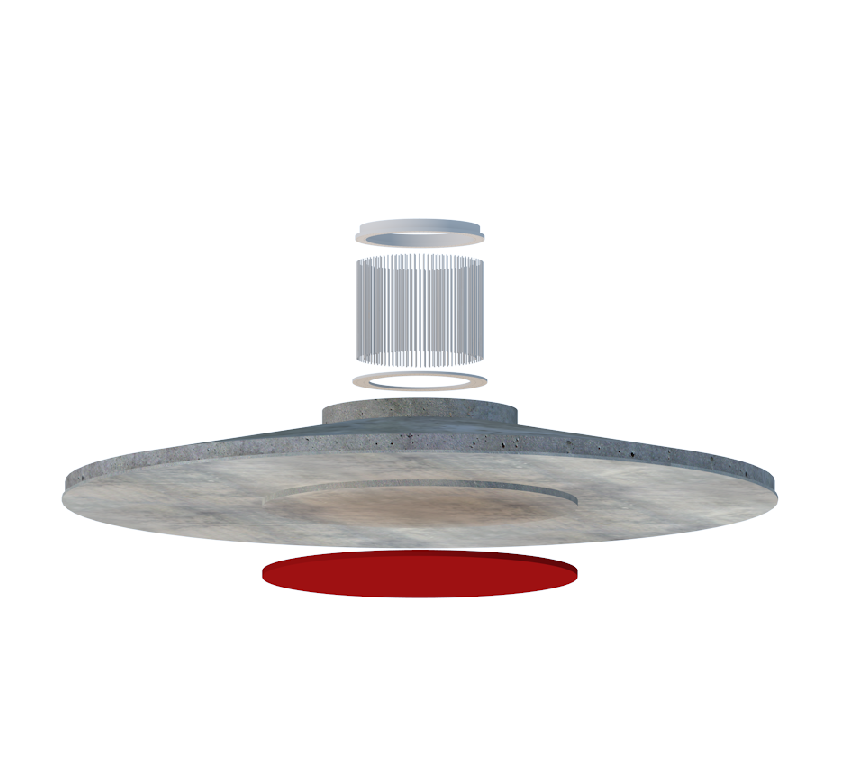

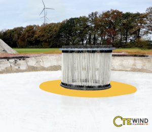
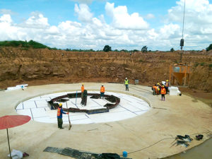
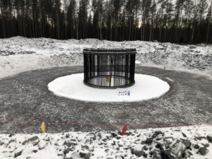
Le SOFT-SPOT® a été développé par l’équipe d’ingénieurs de CTE Wind et est mis en œuvre dans différents pays du monde. Cette conception de fondation éolienne optimise le bilan quantitatif car elle permet d’économiser du béton, des barres de renfort et de réduire le diamètre de la fondation. Elle est facile à construire et la construction de la fondation gravitaire n’est pas modifiée. Un brevet a été déposé.
CTE Wind a déjà développé et mis en œuvre plusieurs projets depuis le lancement du SOFT-SPOT®. Des centaines de nouvelles fondations avec SOFT-SPOT® ont été construites dans le monde entier : Brésil, France, Lituanie, Indonésie, Mexique, Pays-Bas, Russie, Serbie, Suède et Thaïlande, pour n’en citer que quelques unes. Grâce à sa conception étonnante, les projets permettent d’économiser jusqu’à 15% de volume de béton, de réduire le diamètre des fondations et le poids total des barres de renfort de 2 à 5%. Dans certains cas, la surface disponible est encore plus importante que le coût des matériaux : avec SOFT-SPOT®, vous avez besoin de moins de surface pour les fondations. Les coûts de temps et d’excavation sont ainsi réduits.
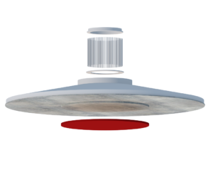
CTE WIND Civil Engineering présente au marché un nouveau système de fondation pour les éoliennes, une fondation à faible gravité avec SOFT-SPOT®. En plaçant une couche de matériau souple sous la partie centrale de la fondation, la dalle agira efficacement comme une fondation en anneau en ce qui concerne l’interaction entre le sol et la structure. La pression d’appui de l’éolienne est concentrée sur le bord de la dalle avec une surface de contact annulaire. Cela augmente la stabilisation du moment avec un bras de levier supplémentaire. Par conséquence, le diamètre de la fondation peut être réduit par rapport à une solution de fondation standard.
Grâce à la conception intelligente SOFT-SPOT®, moins de travaux d’excavation sont nécessaires. Cela réduit le coût des machines. En outre, la construction de la couche souple ne nécessite aucune formation supplémentaire des ouvriers du chantier. La construction est très facile et le matériau pour la couche souple peut être acheté à bon marché dans le monde entier. Ou, comme l’a souligné le client de CTE Wind, H4a Windenergie B.V : C’est tout simplement la fondation la plus économique que vous pouvez choisir.
Contactez-nous si vous souhaitez en savoir plus sur la solution SOFT-SPOT® de CTE Wind.
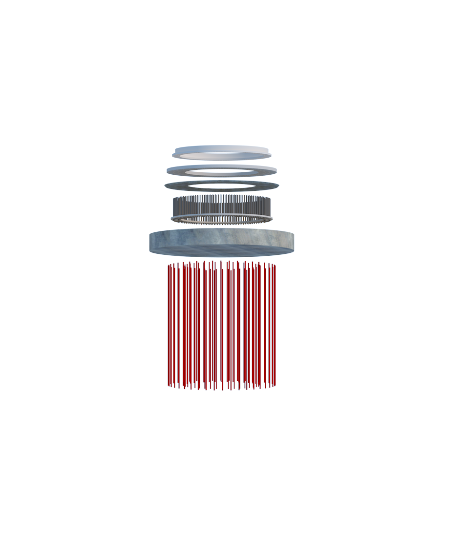

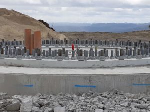
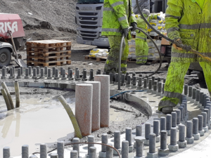
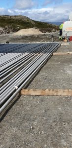
L’ancre de roche est une solution de fondation complexe mais efficace. Elle réduit les volumes de béton et d’acier en utilisant le rocher comme fondation principale. L’ancre de roche est très rentable, réalisable et s’est avérée d’être très fiable dans plusieurs projets.
Cette solution utilise les masses rocheuses comme fondation des éoliennes. En gros, la tour est posée sur le sommet d’un petit bloc de béton armé.
Deux options sont possibles :
Les ancres neutralisent les forces de soulèvement agissant sur les fondations et mettent les structures en béton sous tension contre la roche. Les ancrages ont souvent une longueur de plusieurs mètres environ.
Les propriétaires de parcs éoliens peuvent profiter du sol terrestre au lieu de construire des fondations gravitaires pour leurs éoliennes. Les coûts du béton armé et des travaux de construction peuvent être économisés.
Les ancrages au sol et les ancrages au rocher offrent une capacité de charge très élevée et la longueur de liaison peut simplement être augmentée pour s’adapter à la charge requise. Les ancres n’impliquent pas de grandes zones d’excavation comme l’exigent les méthodes alternatives et constituent une option particulièrement intéressante lorsque l’espace est limité et que l’impact ou l’environnement est une priorité.
Cette solution est particulièrement complexe car les ingénieurs doivent adapter la fondation, avec une interface, entre les tours et les ancrages dans le rocher. Sans oublier le travail de conception spécifique à réaliser pour ces ancrages.
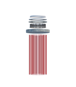
Les ancrages de roche sont faits d’acier à haute résistance et sont généralement ancrés dans un substrat rocheux sain au moyen d’un coulis à haute résistance. Des conduits sont placés dans le béton et des trous seront percés dans la roche pour l’application de la post-tension.
Les ancrages peuvent être des boulons ou des câbles. Pour la plupart des applications, les ancrages de roches sont tendus à une force supérieure à celle qui est nécessaire pour résister à la force de soulèvement de la fondation. Ils sont finalement coulés sur une partie de leur longueur pour permettre une certaine longueur de tension libre.
Contactez-nous si vous souhaitez en savoir plus sur la solution d’ancrage et d’adaptation au rocher de CTE Wind.
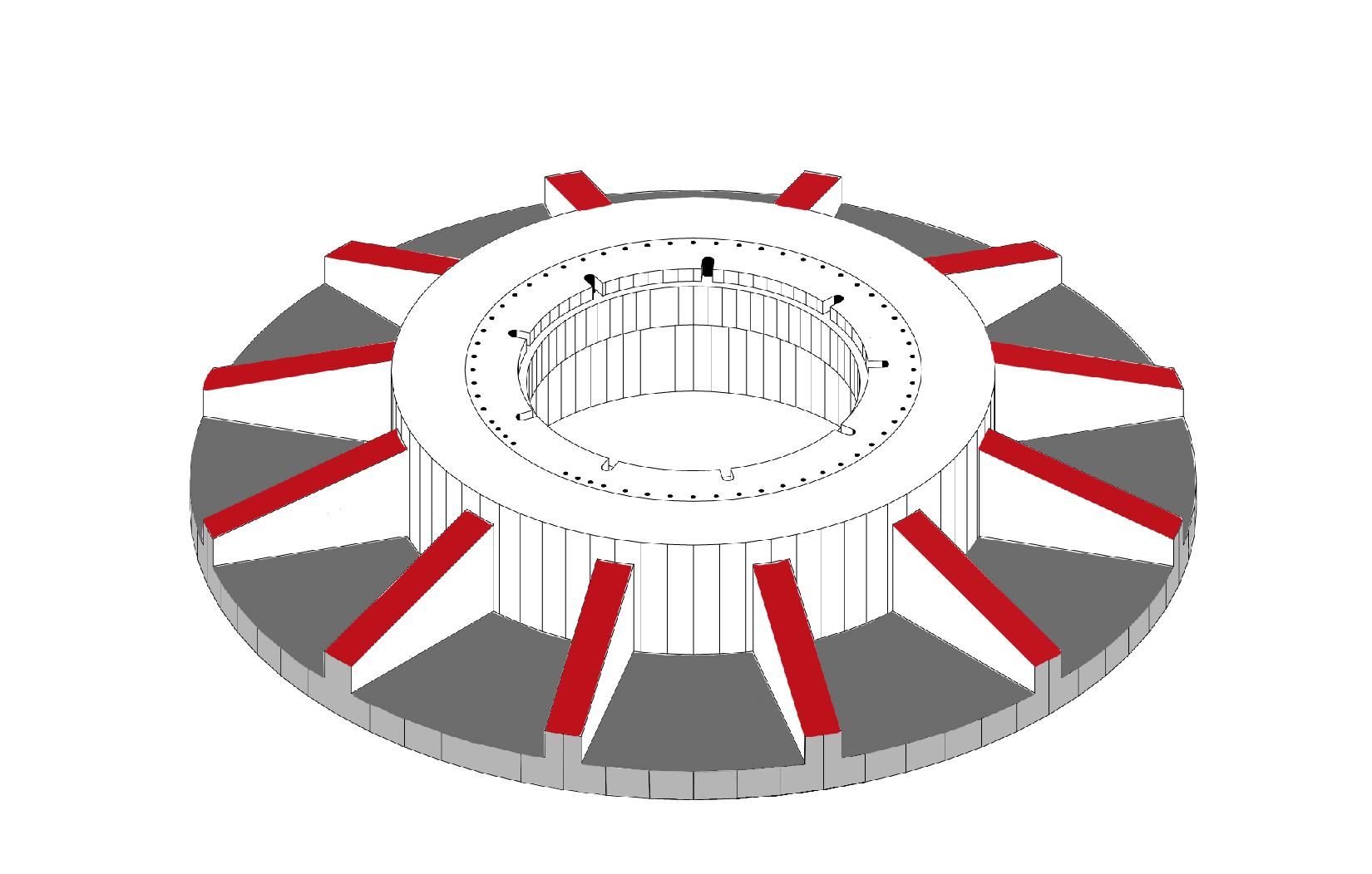

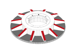
La solution de fondation en forme d’étoile consiste en une fine dalle, un piédestal au centre de la fondation et six à douze bras qui renforcent la dalle. L’économie est estimée à 40 % du volume de béton.
La fondation en forme d’étoile est une variante de la fondation gravitaire classique. Des volumes considérables de béton sont remplacés par du remblai.
Aussi prometteurs que les avantages de ce design intéressant puissent paraître à première vue : les travaux de fragmentation compliqués s’opposent aux économies de béton. C’est pourquoi cette solution présente ses principaux avantages, en particulier lorsque les coûts du béton sont beaucoup plus élevés que les coûts de la main-d’œuvre. Techniquement, cette solution fonctionne sur des terrains où les contraintes du sol sont faibles.
Cette solution pourrait être protégée par divers brevets dans et à partir de certains pays. Souvent, le brevet porte sur des parties de murs préfabriqués.
Il convient donc de vérifier quelle est l’approche la plus adéquate.
Contactez-nous si vous souhaitez en savoir plus sur la fondation en forme d’étoile de CTE Wind.
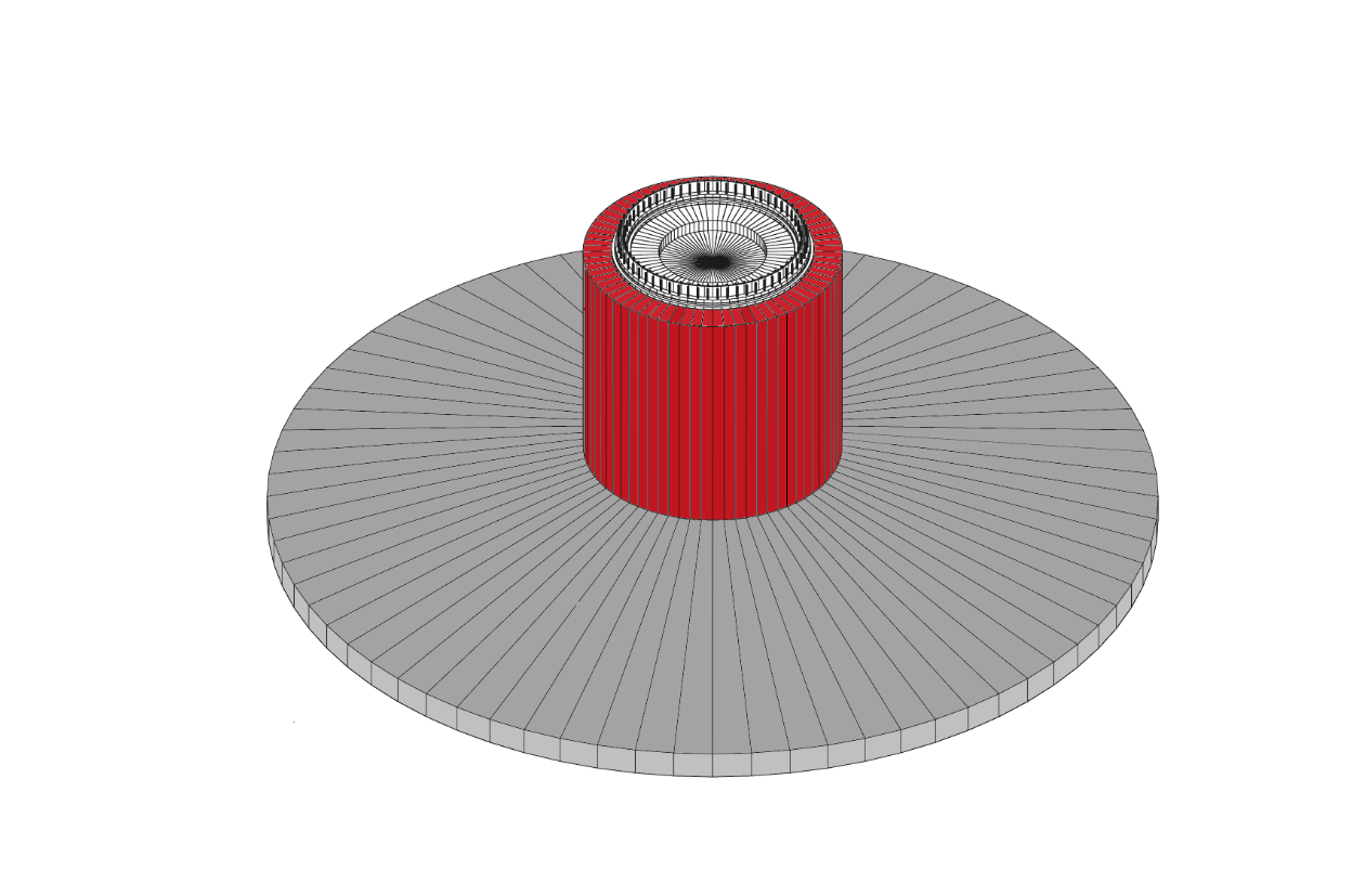

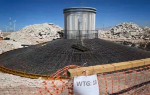
Cette fondation traditionnelle avec un socle rehaussé permet d’atteindre des hauteurs de moyeu plus élevées lorsque la tour est trop courte. Cela permet d’augmenter la productivité de l’éolienne.
L’idée de cette fondation est d’atteindre une hauteur de moyeu plus élevée avec un piédestal surélevé. La tour se dresse de 3 à 6 mètres au-dessus du “niveau du sol”. La tour ne subit aucune modification et la construction de la fondation ne nécessite pas de grues plus grandes.
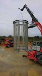
Idéalement, cette solution est combinée avec une cage d’ancrage plus longue afin que le piédestal et la dalle soient bien reliés pour éviter des fissures.
Les ingénieurs de CTE Wind peuvent concevoir la cage d’ancrage et préparer le plan détaillé de la cage d’ancrage.
La fondation à piédestal rehaussé a déjà été testée et mise en œuvre dans différents projets en Europe et en Amérique latine.
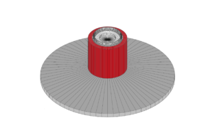
La vitesse du vent à des altitudes plus élevées est parfois bien supérieure à celle du sol. C’est pourquoi il est plus avantageux de placer l’éolienne plus haut, là où il y a plus d’énergie à extraire.
La solution avec socle rehaussé permet, grâce à sa hauteur de moyeu plus élevée, de capter des vitesses de vent plus rapides et plus stables. Mais non seulement. En augmentant la hauteur des moyeux, l’éolienne est capable de porter des pales plus grandes et plus longues. Ce qui signifie une plus grande efficacité aérodynamique pour la même machine en conservant la même longueur de tour.
Contactez-nous si vous souhaitez en savoir plus sur la fondation avec socle rehaussé de CTE Wind.
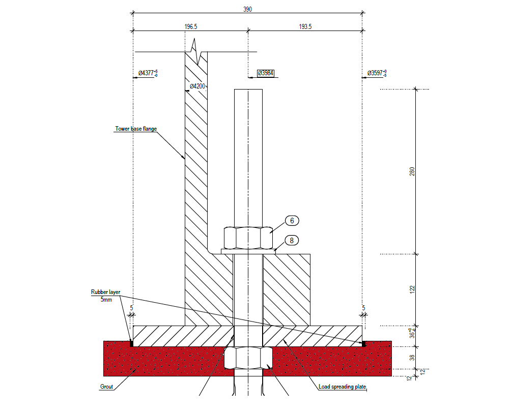

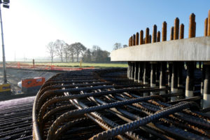
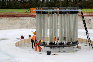
La solution de conception des cages d’ancrage permet d’optimiser le dimensionnement des fondations et donc la quantité de béton et d’acier nécessaire.
Aux États-Unis, un service obligatoire de l’ingénieur chargé de la structure, en Europe, fourni par les fabricants d’éolien : La cage d’ancrage. Une cage d’ancrage bien conçue, ou cage à boulons, permet d’optimiser le volume des fondations d’une éolienne (WTG). Ce savoir-faire particulier de la conception de la cage d’ancrage interne amène CTE Wind à proposer des solutions de fondation sophistiquées telles que l’adaptateur de rocher ou la fondation avec un socle rehaussé. Ce dernier permet d’atteindre des hauteurs de moyeu plus élevées. La tour se dresse de 3 à 6 mètres au-dessus du “niveau du sol”. La solution idéale prévoit également la conception de la cage d’ancrage. L’équipe d’ingénieurs de CTE Wind développe la cage et détermine la longueur des boulons, les charges de précontrainte, la qualité de l’acier et tous les autres paramètres nécessaires.
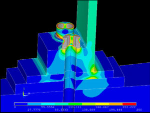
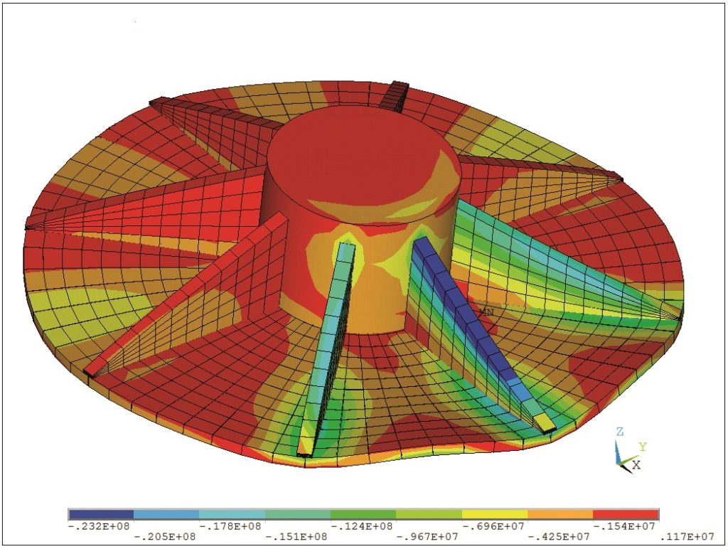
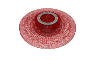
Le CTE Wind utilise pour la conception des cages d’ancrage la méthode des éléments finis (FEM) qui permet d’analyser le comportement des structures à géométrie complexe et à fortes charges. L’image ci-dessus montre la répartition des contraintes dans un raccordement à la cage par une bride de base de la tour. Des modèles comme celui-ci permettent de vérifier l’intégrité structurelle. La méthode FEM, combinée au savoir-faire de CTE Winds, permet – en cas de problème pendant la phase de construction – de trouver des solutions de réparation. Plusieurs clients ont économisé de l’argent et du temps grâce à l’expérience de CTE Wind en matière de pathologie et aux compétences de FEM.
Contactez-nous si vous souhaitez en savoir plus sur la conception de la cage d’ancrage de CTE Wind.
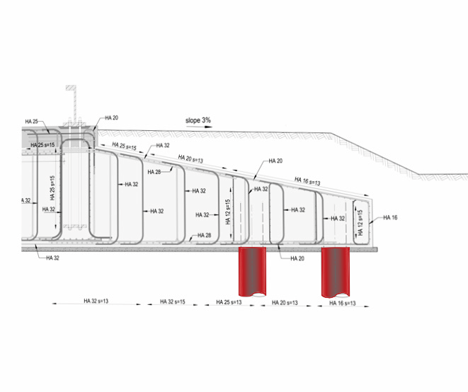

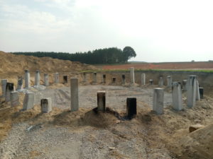
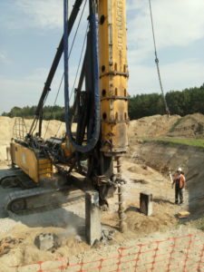
Pile foundation transfer the load coming from the wind turbine foundation to the lower-lying ground thereby providing overall support to the structure. A pile foundation solution takes into account any type of piles (driven, precast, etc.).
A pile is basically a long cylinder or prism of reinforced concrete or a tube of steel that is placed in the ground to transfer the loads coming from top structure by friction or cap resistance.
Pile foundations are used in wind parks where the soil cannot bear the compression or tensile loads applied by the wind turbine.
The piles have to carry concentrated loads and are subject to fatigue loads, too. That is why piles must be designed carefully by study the soil reports drilling logs.
Some geotechnical experience is a must to be able to understand and interpret correctly!
Every pile has an area of influence in the ground around it which can also vary from one soil layer to the next.
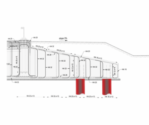
Piles are long, slender columns. They can be determined as single elements but also as pile groups.
Once their dimensions vary under the same foundation cap – length or diameter – their stiffness will also change and then the design becomes a new dimension due to possible differential settlements.
A pile reinforcement drawing will be prepared.
In our current projects, piles length was found from 10 m to 70 m.
Please contact us if you are interested in knowing more about CTE Wind’s pile foundation.
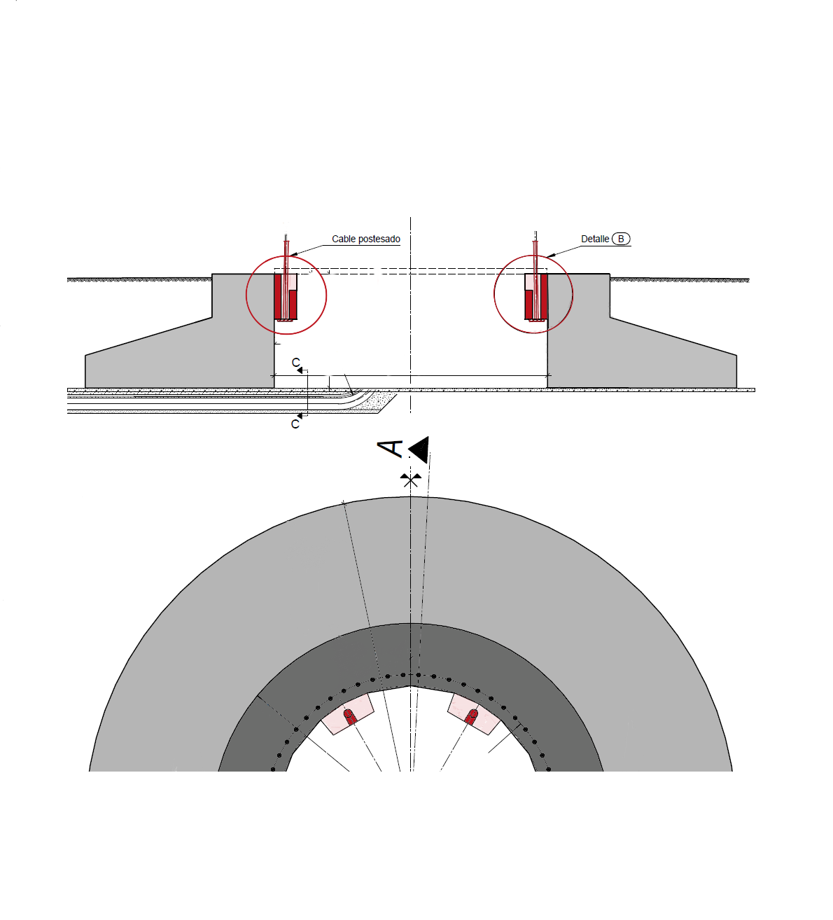

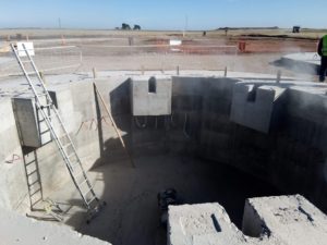
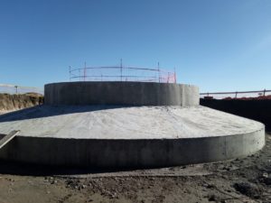
The hollow foundation solution allows the reception of anchor cables for concrete towers. The tower is anchored trough pre- or post-stressed cables to the foundation.
Even if there are variants where the concrete tower sits directly on a classic slab foundation, most towers have a foundation with a cellar. Cables will be anchored here and the tools to apply the pre- and post-stress loads will be positioned there, too.
The reinforcement design changes a fair amount in comparison to standard gravity foundations. Beside the interior shatter work a special attention has to be paid to the anchoring of the cable heads, were concentrated loads will be introduced massively to the concrete in a very limited space.
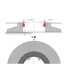
The lower surface of the foundation acts as a ring, therefore the higher weight of the tower help to stabilize the entire structure. Some special attention need the lid, to close the opening on top of the foundation. Special arrangements have to be taken to seal the lower part of the foundation against incoming water.
Please contact us if you are interested in knowing more about CTE Wind’s hollow foundation.
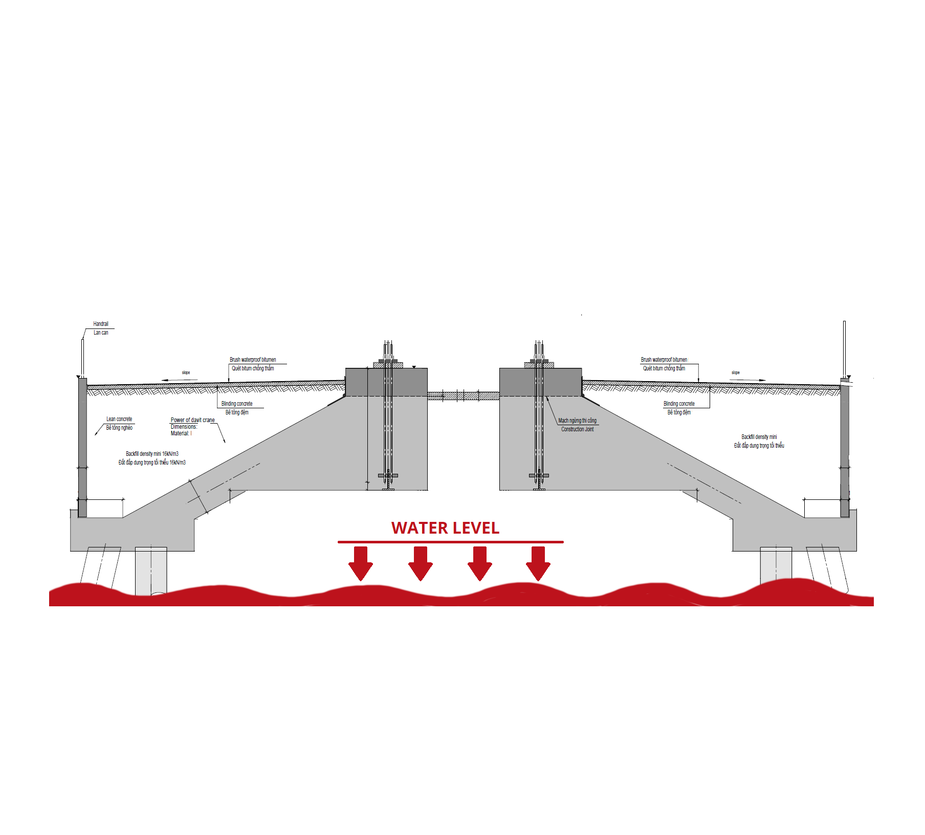


The nearshore foundation is a proven solution in intertidal regions. During the low tide the foundation is exposed to the air and submerged in seawater at high tide. On sandy beaches with muddy underground the foundations can require piles up to 70 meters length.
CTE Wind’s special solution allows to save about 30 percent of the construction costs due to the astonishing design and compared to similar projects from third parties.
The solution provides a circular, cone like foundation on top of piles which are designed in-house. To tackle the challenging environmental criteria for geotechnics, tides, waves and ship movements close to the platforms, the patented foundation takes also the feasibility into account
CTV, the Asiaese office of CTE Wind, has already designed five wind farm projects with its patented solution.
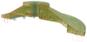
As nearshore is the area from the swash zone to the position marking the start of the offshore zone defined. Typically, the water depths in nearshore areas are up to of 20 meters. In intertidal zones the water level can change massively between 5 – 15 meters during high and low tide. It is located on marine coastlines, including rocky shores and sandy beaches.
Please contact us if you are interested in knowing more about CTE Wind’s nearshore foundation.
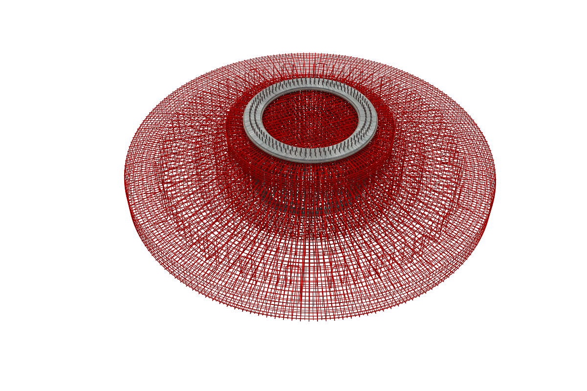

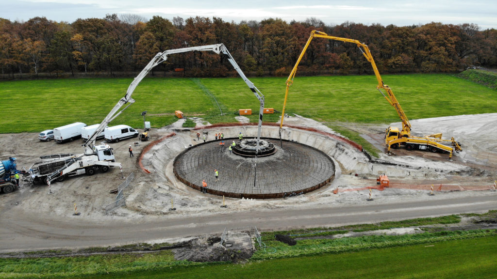
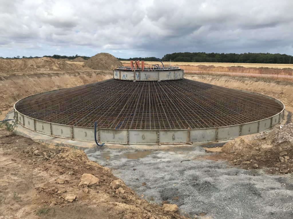
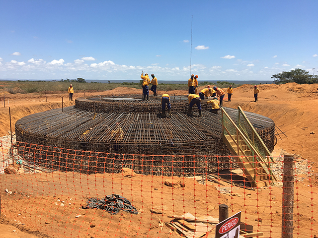
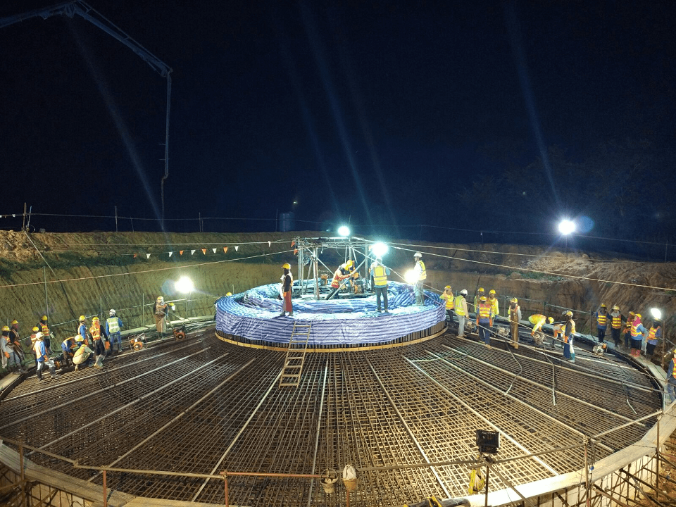
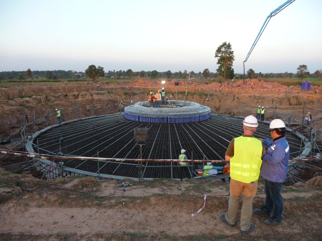
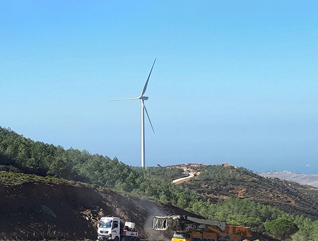
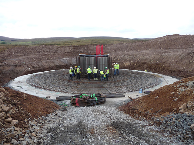
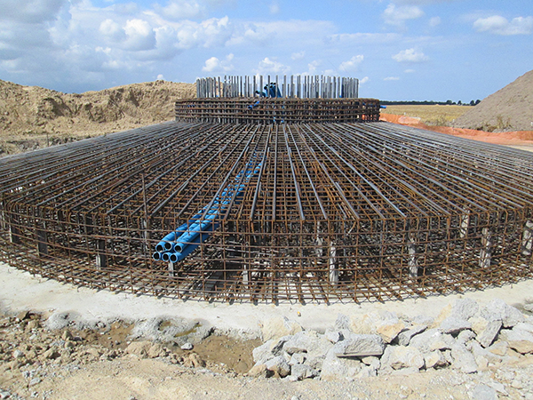
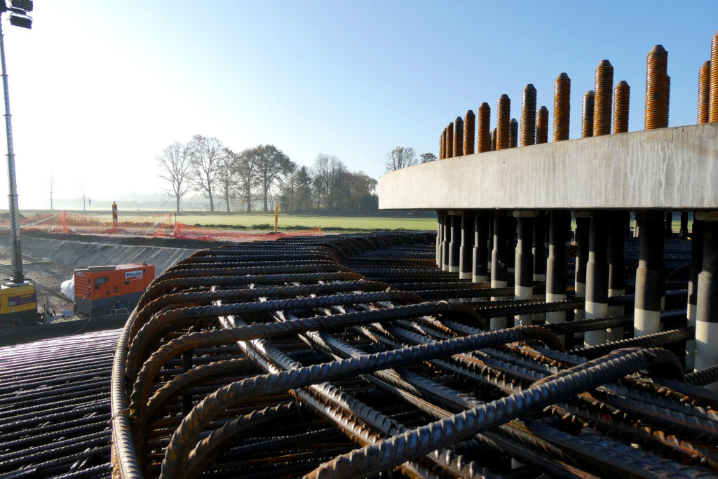
The design of this solution consists of a slab foundation for a steel or a concrete tower. It is the most common form of a foundation for wind turbines but yet remains a complex structure.
Wind turbine generators (WTG) are becoming more and more powerful and the hub heights are increasing by the day. As a result, the concrete volume can reach these days to more than 1000 cubic metres per foundation.
CTE Wind has optimized the bill of quantities massively over the last decades. And still is continuing by means of research to work on effectful improvements with the main objective to deliver resource-savings but reliable design solutions.
The significant advantages of CTE Winds gravity foundation are:
CTE Wind continuously improves this standard solution. On one side by taking into account the developments of the turbine manufacturers (size and performance) and on the other hand through close cooperation in research and developments projects (Tower manufacturer, universities, standardization bodies etc.). The major purpose is to cut down the minimal concrete resistance class and to reduce the required amount of steel and concrete. Also improvements trough non-linear calculations.
CTE Wind addapt his gravity foundation to the existing soil conditions. Thus several variants of this standard slab solution exists. Furthermore it can be combined with other CTE Wind design solutions, such as the SOFT-SPOT®. The customer is not spoilt for choice. He will be supported and advised throughout the entire project by experienced geotech and civil engineers.
Please contact us if you are interested in knowing more about CTE Wind’s gravity solution

Pour vous fournir des services, améliorer votre expérience sur le site, le sécuriser, analyser le trafic, vous proposer des publicités et des contenus adaptés à vos centres d'intérêts, et enfin vous permettre de partager des articles sur les réseaux sociaux
| Cookie | Duration | Description |
|---|---|---|
| cookielawinfo-checbox-autres | 11 mois | Ce cookie est généré par GDPR Cookie Consent plugin et est utilisé pour recueillir le consentement ou non de l'utilisateur dans l'utilisation de cookies de la catégorie "Autres". |
| cookielawinfo-checbox-mesure-daudience | 11 mois | Ce cookie est généré par GDPR Cookie Consent plugin et est utilisé pour recueillir le consentement ou non de l'utilisateur dans l'utilisation de cookies de la catégorie "mesure-daudience". |
| cookielawinfo-checkbox-essentiels | 11 mois | Ce cookie est généré par GDPR Cookie Consent plugin et est utilisé pour recueillir le consentement ou non de l'utilisateur dans l'utilisation de cookies de la catégorie "essentiels". |
| cookielawinfo-checkbox-fonctionnement | 11 mois | Ce cookie est généré par GDPR Cookie Consent plugin et est utilisé pour recueillir le consentement ou non de l'utilisateur dans l'utilisation de cookies de la catégorie "fonctionnement". |
| cookielawinfo-checkbox-performances | 11 mois | Ce cookie est généré par GDPR Cookie Consent plugin et est utilisé pour recueillir le consentement ou non de l'utilisateur dans l'utilisation de cookies de la catégorie "performances". |
| PHPSESSID | session | Ce cookie est natif aux applications php. Il est utilisé pour stocker et identifier le session_id unique affecté à chaque utilisateur et indispensable aux scripts du site Internet. Ce cookie de session détruit quand les navigateur est fermé. |
| viewed_cookie_policy | 11 mois | Ce cookie est généré par GDPR Cookie Consent plugin et est utilisé pour recueillir le consentement ou non de l'utilisateur dans l'utilisation de cookies. Il ne recueille aucune donnée personnelle. |
| _GRECAPTCHA | 5 mois 27 jours | Ce cookie est créé par Google. En plus de certains cookies génériques, reCAPTCHA génère un cookie pour protéger les différents formulaires du sites contre les robots. |
| Cookie | Duration | Description |
|---|---|---|
| pll_language | 1 an | Ce cookie est installé par Polylang plugin for WordPress powered websites. Le cookie stock le code langue de la dernière page consultée. |
| Cookie | Duration | Description |
|---|---|---|
| _gat | 1 minute | Ce cookie est installé par Google Universal Analytics pour limiter le taux de requêtes afin de limiter la collecte de données sur les sites à fort trafic. |
| Cookie | Duration | Description |
|---|---|---|
| _ga | 2 ans | Ce cookie est installé par Google Analytics. Le cookie est utilisé pour compter les visiteurs, les sessions et les données de campagnes analytics utilisées dans les rapports. Les cookies sont stockés de façon anonyme et identifiés par un nombre généré de façon aléatoire. |
| _gat_gtag_UA_151427895_1 | 1 minute | Ce cookie est installé par Google tag manager pour limiter le taux de requêtes afin de limiter la collecte de données sur les sites à fort trafic. |
| _gid | 1 jour | Ce cookie est installé par Google Universal Analytics. Le cookie est utilisé pour stocker les informations d'utilisation du site internet par l'utilisateur et aide à créer des rapports de santé du site internet. Les données collectées incluent le nombre de visiteurs, d'où ils viennent, et les pages qu'ils visitent dans un formulaire anonyme. |


